
1) Introduction
This tutorial is intended to guide new users with no previous experience using bambu. It will guide through all the necessary steps, starting from a C source application, explaining the different ways to use bambu, and showing how to generate and synthesize a working Verilog design.
2) Preliminaries
For this tutorial it will be assumed that you the bambu sources have already been downloaded from here and successfully configured and installed it, following the procedure described here. It is also assumed that the installed binaries are in the search path, so that it is possible to run bambu from the command line without specifying the full path. This can be checked by running the following command in a terminal.
$ bambu --version
If everything is fine, the output is the following (the last couple of lines may change depending on the version):
*******************************************************************
                 ____                  _
                | __ )  __ _ _ __ ___ | |_   _   _
                |  _ \ / _` | '_ ` _ \| '_ \| | | |
                | |_) | (_| | | | | | | |_) | |_| |
                |____/ \__,_|_| |_| |_|_.__/ \__,_|
*******************************************************************
                     High-Level Synthesis Tool

                    Politecnico di Milano - DEIB
                     System Architectures Group
*******************************************************************
            Copyright (c) 2004-2020 Politecnico di Milano
Version: PandA 0.9.6
In the rest of the tutorial, some examples that are already included in the bambu sources that you have downloaded will be used. Most of the tutorial does not require any vendor tool to be installed and configured along with bambu. However, to execute some common scenarios, some extra tools have to be installed. In particular:
- Section 4) shows how the generated design can be simulated and validated within the bambu HLS flow. This section assumes that at least one of the supported simulators is available that bambu was correctly configured to use the simulator. The configuration options for the simulators are explained here.
If commercial simulators are not available, one of the supported Open Source simulators can be used: Icarus Verilog and Verilator. They are usually distributed as standard packages in the most common Linux distributions, with the namesiverilogandverilatorrespectively. Since they do not support mixed simulation and since the generated testbenches are written in Verilog, this will be used as the target language in the examples of this tutorial. However, bambu is also able to generate VHDL as it will be shown in Section 9 of the tutorial. - Section 5) shows how to use bambu for a complete synthesis flow. The tool starts from a C source code application, it generates the Verilog, and then it automatically invokes the synthesis tool for logic synthesis, technology mapping, place, and route. The synthesis tools are strictly dependent on vendors and target devices and bambu has to be properly configured to use them. The supported synthesis tools are described in the installation instructions, along with the configuration options to enable them.
All the other examples presented in the tutorial do not require any additional tools. If some of the described procedures does not work out as expected, please report it to this google group or send an email to panda-info@polimi.it.
3) Basic Usage – Generation of a Verilog design from C sources
The first example that will be presented is based on the CRC code. Initially enter the directory containing the example files.
$ cd BAMBU_SOURCE_ROOT_DIR/examples/crc
The directory contains the C source file for our example spec.c, along with a number of shell scripts and other auxiliary files.
Now create your own tutorial directory (where you will work from now on), and enter into it.
$ mkdir tutorial
$ cd tutorial
Working in a separate directory is not required, but it is advised for this tutorial because bambu generates a bunch of files during its execution. Keeping them in a separate place will help us to get acquainted with bambu‘s output, without mixing it with other stuff.
bambu can be now run for the first time.
$ bambu ../spec.c
This operation launches the default High-Level Synthesis (HLS) flow: a Verilog design will be generated from the ../spec.c source file.
After the execution, the tutorial directory will contain some files.
$ ls
0_array_ref_22490.mem
0_array_ref_23102.mem
array_ref_22490.mem
array_ref_22670.mem
array_ref_22695.mem
array_ref_22746.mem
array_ref_22775.mem
array_ref_23102.mem
HLS_output/
synthesize_Synthesis_main_minimal_interface.sh
top.v
Note that the indices contained in the names of the .mem files produced by bambu can be different on different systems.
top.v contains the Verilog design generated by bambu for the C program. It is not very straightforward to read, because it’s machine-generated and it is not intended to be human-readable.
With default options bambu does not trigger any kind of simulation, nor it invokes vendor tools for the synthesis. Nevertheless, it generates synthesize_Synthesis_main_minimal_interface.sh shell script which can be used from the command line to launch the vendor tools for the synthesis. Since the target FPGA was not specified, bambu generated scripts targeting the default device (xc7z020,-1,clg48). The details on how to select the target device will be later provided in the tutorial.
HLS_output is a directory where bambu places different results. It contains a Synthesis subdirectory with some empty subdirectories (input and output), a .tcl script to launch the synthesis and a .sdc file containing the design constraints. They will be used when the synthesis is executed, and the input and output directories will be filled with the necessary stuff by the synthesize_Synthesis_main_minimal_interface.sh script.
Finally, all the *.mem files contain data for the initialization of the memories.
In this example, a single C file is used, but the same command can be used to synthesize multiple source files at the same time to generate a single design. Most of the typical C compiler options can be used with bambu.
For example optimizations can be enabled by using -O0, -O1, -O2, -O3, -Os or you can specify include directories with -I<include_directory_name>, so that all the necessary headers are correctly found.
The High-Level Synthesis flow can be limited to a subset of functions present in the C file. For example, in spec.c file, the main() is only calling icrc() multiple times to test it. It may make sense to generate an hardware accelerator only for the icrc() function.
This is possible with bambu, using the command line option --top-fname=<function_name>, like this:
$ bambu ../spec.c --top-fname=icrc
This will generate a new icrc.v Verilog file in the current directory, along with a new synthesize_Synthesis_icrc_minimal_interface.sh shell script for the synthesis, and another subdirectory of HLS_output/Synthesis/ to handle this.
The result is that main() is not synthesized and a smaller core implementing only the icrc() functionality is produced.
4) Simulation
Before actually starting the synthesis, it is possible to simulate the generated design. The C source code is compiled and executed with randomly generated inputs or with user-provided inputs. The execution of the C program returns a result which is compared with the result produced by the simulated Verilog: if they match the co-simulation succeeds, otherwise it fails and the difference is reported to the user.
This section will show how to perform and control the co-simulation workflow.
The basic bambu invocation for simulation is the following.
$ bambu ../spec.c --simulate --simulator=VERILATOR
This command invokes the bambu with the default HLS flow, but after the generation of the HDL design, the co-simulation flow is automatically started and performed with Verilator.
The --simulate flag enables co-simulation, while --simulator=YOUR_FAVORITE_SIMULATOR tells bambu which simulator to use.
Valid strings for YOUR_FAVORITE_SIMULATOR are:
VERILATORICARUSMODELSIMXSIM(the Xilinx simulator provided with Vivado)ISIM(the Xilinx simulator provided with ISE)
If none of the above is specified and you simply pass --simulate, bambu selects one by default. Remember that you need to have bambu configured with the proper options to the configure script and to have the correct simulator installed in order to use it. See panda installation for information on how to do it. In the remainder of the tutorial VERILATOR is used. Be careful because it does not support VHDL.
In general, one should provide input values for the simulation. If they are not specified, bambu generates them randomly and saves them in a test.xml file in the current working directory. In this example, given that main() has no arguments the test.xml file is an empty stub, like this:
$ cat test.xml
<?xml version="1.0"?>
<function>
 <testbench/>
</function>
bambu also generates a short report on the simulation cycles:
 Total cycles : 2898 cycles
 Number of executions : 1
 Average execution : 2898 cycles
The report contains information about how many times the design was simulated (1 time) and how many cycles the simulation took to terminate (2898 cycles). The simulation is useful for preliminary functional verification and for performances evaluation. Moreover, the obtained number of cycles can be slightly different on different systems.
To co-simulate the icrc() function, the test inputs cannot be generated randomly, because the parameter unsigned char *lin is a pointer, and the icrc() function assumes that it points to an array of unsigned chars whose length is expressed by the parameter unsigned int len. For this reason, the task of providing meaningful inputs is entirely demanded to the user. The examples provided with bambu already contain the .xml files with the input data. For example, for icrc(), the ../test_icrc.xml file can be used. Its content is the following:
<?xml version="1.0"?>
<function>
 <testbench crc="0" lin="{97,115,100,102,102,101,97,103,101,119,97,72,65,70,69,70,97,101,68,115,70,69,97,119,70,100,115,70,97,101,102,97,101,101,114,100,106,103,112,105,109,50,51,0}" len="40" jinit="0" jrev="1"/>
 <testbench crc="57266" lin="{97,115,100,102,102,101,97,103,101,119,97,72,65,70,69,70,97,101,68,115,70,69,97,119,70,100,115,70,97,101,102,97,101,101,114,100,106,103,112,105,109,50,51,0}" len="42" jinit="-1" jrev="1"/>
</function>
In the tutorial directory created in section (3), bambu can be invoked in this way:
$ bambu ../spec.c --top-fname=icrc --generate-tb=../test_icrc.xml --simulate --simulator=VERILATOR
bambu will create a design for the icrc() function and will start the co-simulation workflow with the input data in ../test_icrc.xml.
test_icrc.xml contains 2 <testbench .../>; nodes. Each of them represents the arguments of a call to the icrc() function. The context is preserved across consecutive calls, both in C and in HDL. In this way, if the first call makes some change in global or static variables, they will be visible in the following calls. This behavior is intended to reproduce the case when a HW module is executed multiple times and it keeps an internal state across multiple executions. With test_icrc.xml the icrc() function is executed two times consecutively. The content of the generated report is:
Total cycles : 2897 cycles
Number of executions : 2
Average execution : 1448 cycles
Differently from the previous report, the number of executions is 2 and the total number of cycles is 2897, with an average of 1448 cycles per execution.
The results.txt file that was created during the execution in your working directory contains a detailed report of the number of cycles for each call.
$ cat results.txt
 1 2725
 1 172
Each line of this file contains data about an execution corresponding to one line of <testbench .../> line in the XML. The first number of every row is the result of the execution (1 for success – 0 for failure) while the second value is the number of the cycles.
5) A Complete Example
After showing how to generate the Verilog design from C, and how to validate it with the co-simulation, a complete example for a real-world use case will be presented.
This example starts with a project with a mix of C and Verilog source files. In this scenario, the Verilog files are hand-written and describe very low-level operations, possibly performing I/O or interfacing with other peripherals (but they can be any kind of user-provided Verilog modules). The C source code, instead, describes at a higher level the whole specification, which has to interface with the Verilog modules to accomplish its functionality. In such a scenario, HLS is used to create a single design where hand-written Verilog modules are integrated with the code generated by bambu starting from the C source code. In particular, it will be shown how to map C function calls onto Verilog modules and, how to use the co-simulation workflow even when hand-written modules are part of the project. Co-simulation of mixed design is possible only if a C golden reference for HDL modules is provided. Finally, it will be shown how to generate the bitstream from the mixed C/Verilog project and how to flash it on a Digilent NEXYS4 evaluation board.
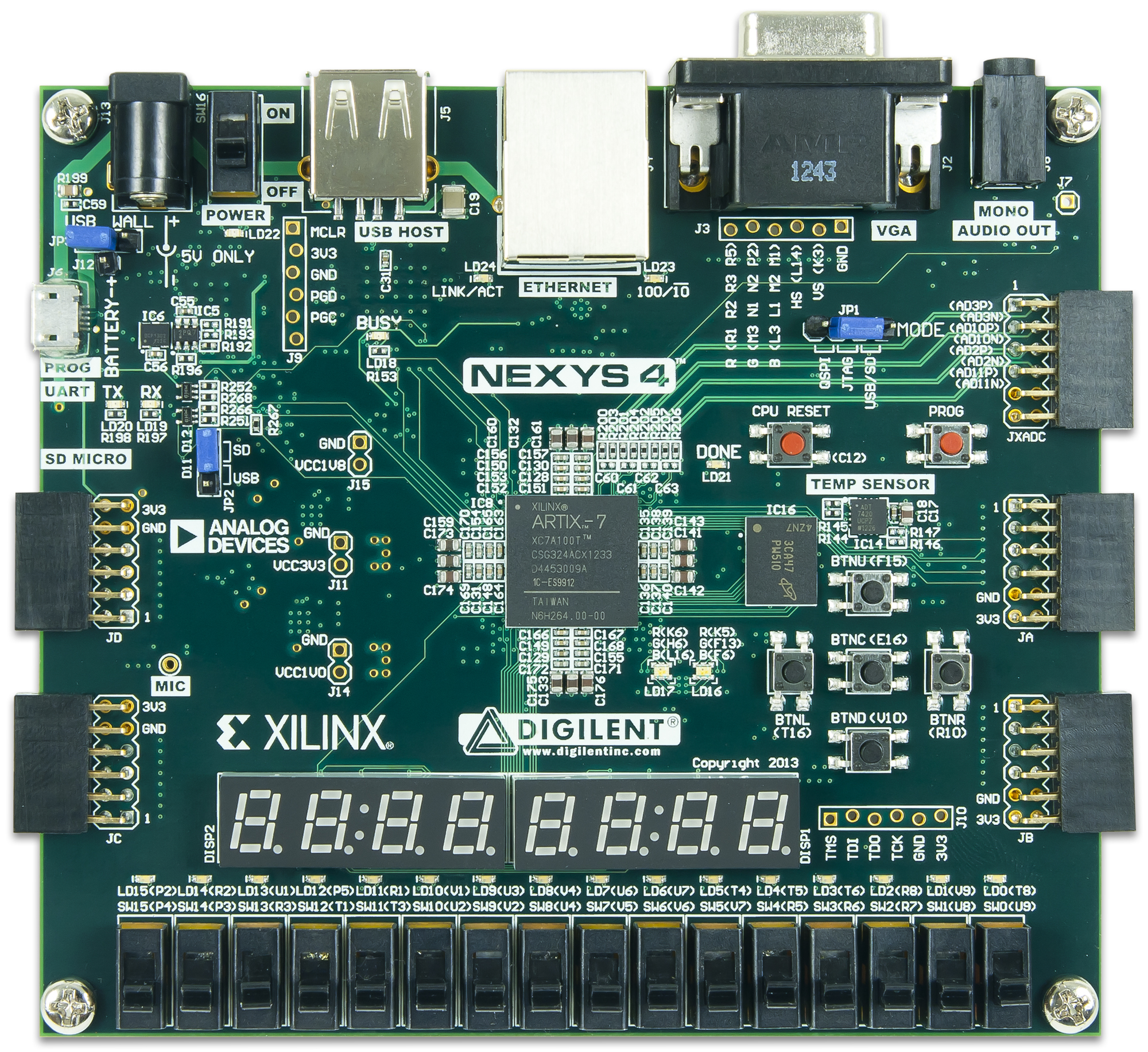
This board contains a Xilinx Artix-7 FPGA, with a wide number of different external interfaces (USB, Ethernet, JTAG, microSD, accelerometer, VGA output, temperature sensor, multiple LEDs, pushbuttons, 7-segment displays, manual switches, and others).
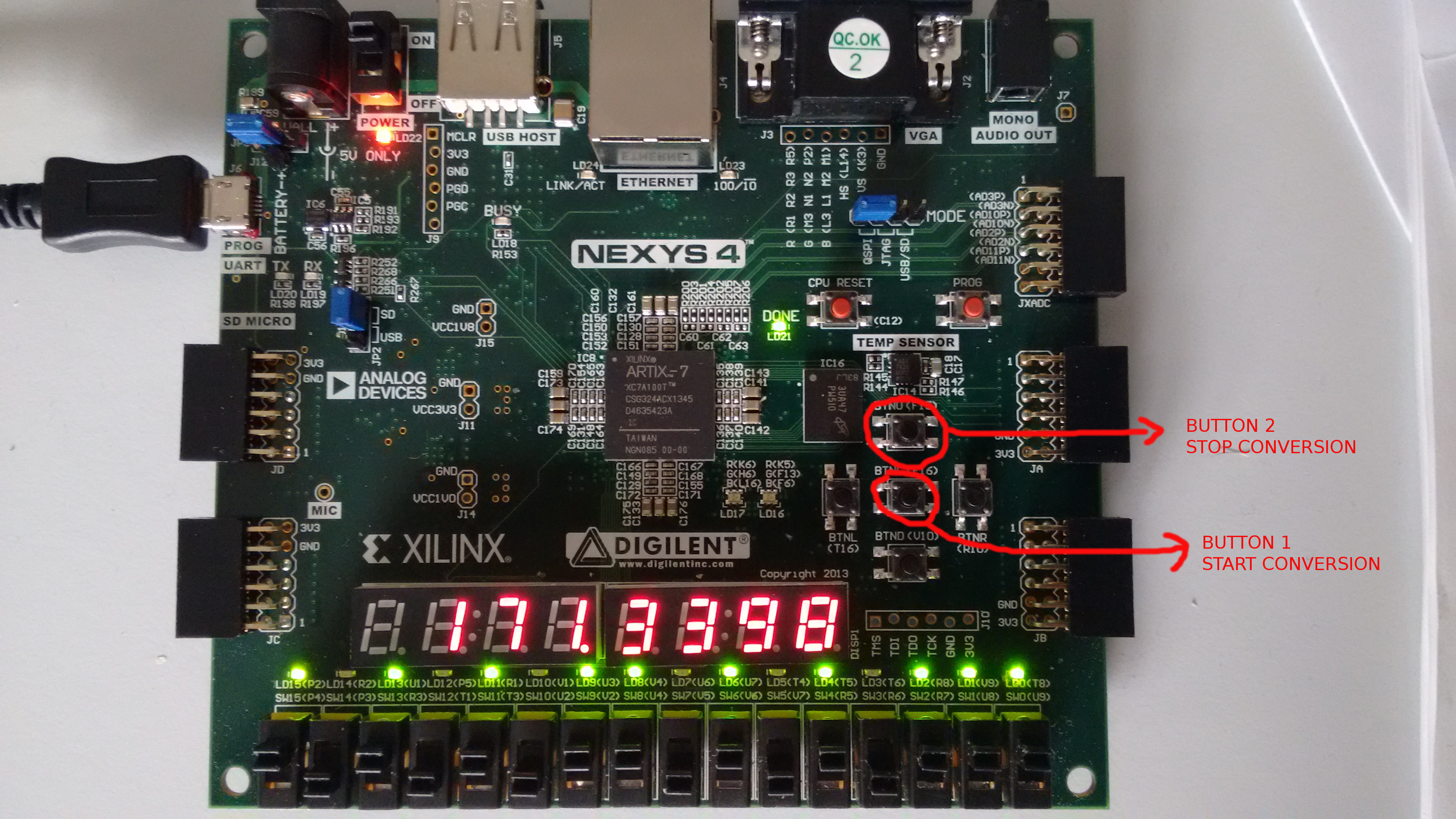
The example aims to build a fixed-point binary-to-decimal converter. The input binary representation is set with the 16 manual switches, and the resulting decimal representation of the number is shown in real-time on the 7-segments displays. For binary representation, an unsigned Q16.16 binary format for fixed-point is used. The first 8 switches on the left in the picture are used for the integer bits, while the 8 switches to the right are used for the fractional bits. As shown in the picture below, when a switch is moved up, the corresponding bit is set to 1 and the green led nearby the switch is turned on. When a switch is moved down, the led is turned off and the corresponding bit is set to 0. At the same time, the decimal representation on the 7-segments display is updated accordingly. The conversion can be controlled with two push buttons, as depicted in the picture. The central button starts the conversion. After the conversion is started every action on the switches directly changes the result on the 7-segments displays. The upper button stops the conversion so that changes of the positions of the switches do not change the value on the 7-segments displays. If the central button is pressed again, the conversion is restarted.
Implementing this accelerator by means of bambu is the final objective of this tutorial.
5.1) Mapping C functions to hand-written HDL modules
The first step is going in the example directory:
$ cd BAMBU_SOURCE_ROOT_DIR/examples/led_example
$ mkdir tutorial
$ cd tutorial
Next step is bambu invocation:
$ bambu ../led_example.c --top-fname=led_example ../IPs.xml
With respect to the previous examples, the significant change is that the file ../IPs.xml is passed to bambu along with the C source code. ../IPs.xml contains a list of cells, in the form <cell>...</cell>. Each of them represents the mapping of a C function onto a Verilog module. Every cell also contains some information on the Verilog module, that will be used for the interconnection with other modules in the design and with external I/O ports during High-Level Synthesis.
In this example, in leds_example.c there are 4 called functions for which the C source code is not provided. These functions are sw_ctrl(), leds_ctrl(), sevensegments_ctrl() and btn_ctrl(). They are defined as extern in separate headers. Their prototypes are the following.
extern unsigned short sw_ctrl();
extern void leds_ctrl(unsigned short val);
extern void sevensegments_ctrl(unsigned long long val, unsigned long long mask);
extern unsigned char btn_ctrl();
Every function acts as a device driver for some peripherals of the board. It has not yet been shown how to specify to bambu how the pins are connected, but this aspect can be ignored for the moment.
The function sw_ctrl() is used to read the position of the manual switches. From the C source code side, it takes no arguments and returns an unsigned short. The returned value is 16 bits wide and every bit represents the position of a manual switch. It takes no argument because the value of the switches will be internally read from some I/O pin.
The function leds_ctrl() controls the LEDs connected to the switches. It takes an unsigned short argument and it returns void. The argument is an unsigned short representing the position of the manual switches. No value is returned, but internally the function sets some I/O pins to power on the LEDs whose corresponding switches are set to “1”.
The function sevensegments_ctrl() drives the 7-segments displays. It takes two unsigned long long arguments: val and mask. These values are used to make the displays show the correct numbers. The specification of the format can be found on the datasheet of the board. Also, this function does not return any value, because the 7-segments displays have no notification mechanism to communicate the success of the operation.
Finally, btn_ctrl() handles the two pushbuttons. It takes no arguments, because the state of the buttons is read from I/O pins, and it returns an unsigned char representing the state of the buttons.
These four modules will not be synthesized from C code, but the already existing Verilog modules will be used: sw_ctrl.v, leds_ctrl.v, sevensegments_ctrl.v and btn_ctrl.v. The information on where are the descriptions of these Verilog modules is contained in IPs.xml.
IPs.xml contains 4 cells, one for every C function that is mapped on an HW module. For every cell, the following information must be specified:
<name>module_name</name>: the name of the Verilog module.<operation operation_name="op_name" [params]/>: the high-level information on the operation that is mapped onto the Verilog module associated with this cell.
"op_name": a string used by the HLS engine during module allocation and binding, to decide which unresolved C function is mapped onto the Verilog module described by this cell.
[params]: a list of assignments in the formpar_name="par_val".
These values are used by the HLS engine for performing the schedule.
bounded="0"specifies that the execution time is unknown or not constant whilebounded="1"specifies that the execution time is known and constant; by default (i.e., if this parameter is not specified) it is assumed that the execution time is constant and known. For a bounded operation, the following quantities have to be specified, depending if the module is pipelined or not. If the module is pipelined the necessary additional parameters are:-
cycles="n", wherenis the total number of cycles for the execution;initiation_time="k", wherekis the initiation time of the pipeline;stage_period="f", wherefis a floating point number representing the execution time (in nanoseconds) of a stage of the pipeline.
If the module is not pipelined the necessary additional parameters are:
-
cycles="n", wherenis the total number of cycles for the execution, greater or equal than 1;execution_time="f", wherefis a floating point number representing the execution time in nanoseconds, it is only meaningful whennis 1, because it allows chaining;
In
IPs.xmlall the modules are bounded and there are both pipelined and not pipelined modules.-
<circuit><component_o id="module_name">[body]</component_o></circuit>: inside this block the port bindings and the Verilog file where the implementation of the module can be found are specified."module_name"must match the"module_name"string used in<name>"module_name"</name>.
The[body]contains several fields. The relevant ones in this example are:<structural_type_descriptor id_type="module_name">: the name of this Verilog module which will be used for its instantiation in other modules.- A list of port specifications. Every port specification has the form
<port_o id="signal_name" dir="direction" [params]><structural_type_descriptor type="type_str" size="n"></port_o>
"direction"can be"IN"or"OUT", depending on the direction of the signal. bambu cannot interface directly C source code with modules withinoutports in Verilog. In C the semantic is always either"IN"(for parameters passed to functions) or"OUT"(for return values of functions).
"signal_name"must match the name of a module port, as specified in the Verilog file containing the description of the module. The in/out direction must match that of the Verilog files.
"type_str"is a string representing the type of the signal. Valid types are"BOOL","INT","UINT"andREAL.
"n"is a positive integer representing the bitsize of the port. It must always be 1 for"BOOL". For the other types it must be the size of the corresponding variable in C.
The order of the specification of the ports must be the same in the Verilog declaration and in the XML description passed to bambu.
– The first port must always be the clock port, so it must be a boolean_port named clock. A special attribute is also used to specify bambu that it is the clock port. The complete XML specification is:<port_o id="clock" dir="IN" is_clock="1"> <structural_type_descriptor type="BOOL" size="1"/> </port_o>
– The second must always be the reset signal. The complete XML specification is:
<port_o id="reset" dir="IN">
  <structural_type_descriptor type="BOOL" size="1"/>
</port_o>
– The third must always be the start_port. The complete XML specification is:
<port_o id="start_port" dir="IN">
  <structural_type_descriptor type="BOOL" size="1"/>
</port_o>
– Then, if the module is not bounded, it is necessary to specify the done_port. The complete XML specification is:
<port_o id="done_port" dir="OUT">
  <structural_type_descriptor type="BOOL" size="1"/>
</port_o>
This port is used for unbounded modules, to signal the caller that the execution has terminated and the results are ready in the return port (if the function return type is not
void).
– The next port to be specified is the return_port. This is the port used to return a value to the caller. For this reason, it is not necessary to specify it if the mapped function has void return type. Theidcan be any name, thedirmust be"OUT"and thetypeandsizemust match the return type of the C function.
– Then it is possible to specify the ports for the parameters of the mapped function. Also, in this case, theidcan be any name, butdirmust be"IN". Thetypeandsizemust match those of the parameters of the mapped function. The mapping of ports to parameter will be done following the specification order.
– Finally, the last ports to be specified are those used to drive global Verilog signals, connected to some external peripherals. In this example, there areledssignal (controlling the LEDs, and others in other modules). All these external global signals must be specified with additional ports. For theledssignal the full XML specification is:<port_o id="done_port" dir="OUT" is_global="1" is_extern="1"> <structural_type_descriptor type="UINT" size="16" /> </port_o>
The
is_globalandis_externparameters will do the trick. <NP_functionality LIBRARY="module_name" VERILOG_FILE_PROVIDED="verilog_filename.v">: this specifies where the Verilog description of the provided module is.
This is the full description of the XML format that can be used to specify to bambu how to map C function calls onto user-provided Verilog modules.
In case you are using external modules written in VHDL instead of Verilog, you simply have to change VERILOG_FILE_PROVIDED to VHDL_FILE_PROVIDED in the xml, and to change the "verilog_filename.v" accordingly to the proper VHDL file name.
Now we can continue with the example. The last command we ran was:
$ bambu ../led_example.c ../IPs.xml --top-fname=led_example
This command performs HLS on led_example.c, specifying to bambu the Verilog binding, but the information provided to the tool is not enough to generate the final accelerator. Indeed, in the generated led_example.v there are some instances of Verilog modules that are used but are not defined. The HLS flow completes successfully, but the generated design cannot be synthesized because the user-defined Verilog modules are not present. So, the command line has to be extended in this way:
$ bambu ../led_example.c ../IPs.xml --top-fname=led_example --file-input-data=../leds_ctrl.v,../sw_ctrl.v,../btn_ctrl.v,../sevensegments_ctrl.v
Here the argument --file-input--data=../leds_ctrl.v,../sw_ctrl.v,../btn_ctrl.v,../sevensegments_ctrl.v tells bambu where to find the definitions of the Verilog modules. The given Verilog files will be copied in the working directory and the synthesis script will be set up to use them.
5.2) Simulation with hand-written HDL modules
Before going on to the generation of the bitstream, one may be interested in checking the correctness of the generated HDL with simulation. Like explained above, bambu has two command-line arguments that can be used to do this: --simulate and --simulator=YOUR_FAVORITE_SIMULATOR. When using simulation, bambu does not just simulate your design, but it also generates automatically the testbench for you, starting from the original specification. The specification is usually the original C code used for HLS. However, in this example, there are some Verilog modules that are not generated with HLS. These modules control the LEDs, the buttons, and basically everything that interacts with the peripherals of the board. Even providing information about the position of Verilog custom modules, the co-simulation cannot be executed since it requires to have the full specification written in C source code. For this reason, it is also necessary to provide a reference C implementation for each hand-written Verilog module. In this way, bambu can compile and execute the C code to provide a golden reference for the co-simulation. To provide the C reference implementations, run bambu as follows:
$ bambu ../led_example.c ../IPs.xml --top-fname=led_example --simulate --simulator=VERILATOR --file-input-data=../leds_ctrl.v,../sw_ctrl.v,../btn_ctrl.v,../sevensegments_ctrl.v --C-no-parse=../leds_ctrl.c,../sw_ctrl.c,../btn_ctrl.c,../sevensegments_ctrl.c
The argument --C-no-parse=../leds_ctrl.c,../sw_ctrl.c,../btn_ctrl.c,../sevensegments_ctrl.c specifies bambu to use also these C source files to create the executable for the co-simulation. However, these files are not used for HLS: the C function calls are still mapped on the user-provided Verilog modules as described in IPs.xml.
This just works but a few subtleties are going on under the hood. Here the C files (passed with the command line option --C-no-parse) mimick in C the behavior of the underlying Verilog modules. If you look into btn_ctrl.c you can see that in the C version the button is always pressed (it always returns 1). Now, when performing the co-simulation with the testbench generated from the C code, bambu expects that the behavior of the HDL is the same as the C code. This is done by checking that the value returned by the C program is the same as the result written on the output port of the generated HW module. In this case, the function we synthesized returns void, so there is actually no value to compare. But the key difference is that software execution terminates because the ‘button’ is pressed. If during the simulation nobody is pressing the button, the simulation runs forever, waiting for the button to be pressed. In this sense, it does not behave like the C code. This situation is handled adding some extra code in btn_ctrl.v, inside the btn_ctrl module:
 // synthesis translate_off
reg [4:0] button_press_countdown = 5'b11111;
wire [4:0] next_button_press_countdown;
assign next_button_press_countdown = button_press_countdown - 1;

always @(posedge clock)
begin
  button_press_countdown <= next_button_press_countdown;
end

always @(posedge clock)
begin
  if (button_press_countdown == 0)
  begin
  out1 <= 1;
  sigTmp <= 1;
  stble <= 1;
  end
end
// synthesis translate_on
Thanks to the directives in the comments, this code is not synthesized. In this way, if you generate the bitstream for the board everything will work as expected with the real buttons.
However, in simulation, you will see that the button is artificially pressed ‘from inside’, so that the Verilog code behaves like expected in co-simulation and bambu is happy.
There are other ways to achieve this, like using delayed assignments in an initial block, always with the translate_off and translate_on directives. This is just an example.
This is an issue you have to bear in mind every time you use co-simulation together with hand-written or third-parties modules.
You always have to provide a C model for co-simulation and make sure that the behavior of the modules not generated with HLS actually matches the behavior of the corresponding C models. Otherwise, the co-simulation will return an error and the flow will not continue.
The other option, if you’re only interested in getting the bitstream on the board and you don’t care about co-simulation, is to skip simulation altogether. You can do it by removing --simulate and --simulator=VERILATOR from the command line and go on to the generation of the bitstream.
5.3) Generation of the bitstream with bambu
Now it is time to set the target device and the design constraints, to generate the bitstream and flash it to the board. Again, you will need to have the vendor tools installed and configured properly to work with bambu. Check the panda installation instructions to see how to do it.
The complete command line for bambu with the options for the Nexys4 board is the following:
$ bambu ../led_example.c ../IPs.xml --top-fname=led_example --file-input-data=../leds_ctrl.v,../sw_ctrl.v,../btn_ctrl.v,../sevensegments_ctrl.v --C-no-parse=../leds_ctrl.c,../sw_ctrl.c,../btn_ctrl.c,../sevensegments_ctrl.c --clock-period=10 --device-name=xc7a100t-1csg324-VVD --evaluation=PERIOD,AREA,FREQUENCY,CLOCK_SLACK,REGISTERS,DSPS,BRAMS ../constraints_STD.xml --backend-sdc-extensions=../Nexys4_Master.sdc
Different options have been added:
--clock-period=10sets the desired clock period to 10 nanoseconds (100 MHz).--device-name=xc7a100t-1csg324-VVDis the Xilinx part number of the target FPGA considered in the example. bambu supports different FPGAs. To see how to add support for new FPGAs, see the discussion on this google group.--evaluation=PERIOD,AREA,FREQUENCY,CLOCK_SLACK,REGISTERS,DSPS,BRAMSlists the metrics that have to be evaluated by bambu during the analysis of the results. Since the listed metrics require synthesis of the generated accelerator, bambu will invoke the vendor tools up to the place and route step to evaluate them. This is also necessary for the generation of the bitstream (that will be performed in a separate step).../constraints_STD.xml: this XML file specifies to bambu that only one copy of the user-provided Verilog modules must be instantiated in the final design. In general, bambu is able to take the decision to duplicate some HW modules to exploit available parallelism, but I/O peripherals cannot be duplicated. In this example, every user-defined module drives some signals to control I/O peripherals, so all of them cannot be duplicated.--backend-sdc-extensions=../Nexys4_Master.sdc: this is a standard Xilinx Design Constraint file, that describes the pin mapping of the Verilog signals. It is necessary to connect the Verilog signals in the driver modules to the correct I/O pins to drive LEDs, switches, pushbuttons and 7-segments displays. The syntax of this file must adhere to the Xilinx SDC syntax, which is an extension of the Synopsys Design Constraints. A detailed description can be found here.
After this final step, the bitstream can be generated and can be flashed to the device. This is accomplished by exploiting the .tcl script provided with the example: program_nexys4.tcl. First, it has to be copied in the present working directory.
$ cp ../program_nexys4.tcl ./
Then it has to be opened and modified changing the directory string at line 2 from synth/HLS_output/Synthesis/vivado_flow/post_route.dcp to HLS_output/Synthesis/vivado_flow/post_route.dcp. Theprogram_nexys4.tcl is not intended to be used from this tutorial and it has to be fixed with the correct path. After fixing the path, the board has to be connected to the PC with the USB cable and it has to be turned on. Finally, Vivado can be invoked to generate the bitstream and to flash it to the device.
$ vivado -mode batch -nojournal -nolog -source program_nexys4.tcl
The Vivado binary must be in the PATH, otherwise the full path of the executable has to be specified. This command will program the board with the result of the High-Level Synthesis flow. The central push button can now be pressed, and the manual switches can now be used to control the LEDs and the 7-segments displays.
If you have any problems please report them on this google group.
6) Additional Information
This tutorial shows a typical use case of bambu covering some of the command-line options, but there are several other options, to select different algorithms and policies for High-Level Synthesis, for tweaking the output to meet the designed needs and other advanced things. All the possible command-line options available in bambu can be listed with the command
$ bambu -h
or
$ bambu --help
For other questions about how the options can be used please feel free to ask for help on this google group or send an email to panda-info@polimi.it.